Blog
This is a private homepage... 100% handcrafted!
Let's get the party started
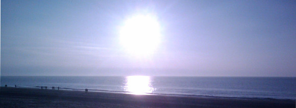
The winter was long, the year began cold... Today I felt a little bit that spring is not far away anymore. \o/
I was at the beach and enjoyed it very much. Energy is back! Let's get the party started! Welcome 2013!
:)
I got a NAS device and installed Linux
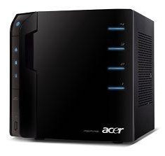 Today a friend gave me his old NAS as a gift... It is an Acer easyStore H340 with 2 x 1TB harddrives. There was a broken Windows installation on it which I directly replaced with the very nice Debian based NAS solution called OpenMediaVault.
I setup the box within some few minutes and it is wonderful. I must say that I installed the OS on an external USB stick because I wanted a mirrored RAID and didn't wanted to insert a 3rd harddrive just for the OS. I will maybe add a small SSD or flash on the SATA bus at some time and will then put the OS there... but only if I am not adding two more harddrives... ;) For now everything is nice like it is.
The web GUI is very clean and easy to use. The RAID was also setup within the web GUI. Everything is just some clicks and you're done... :)
I am happy about this new device!
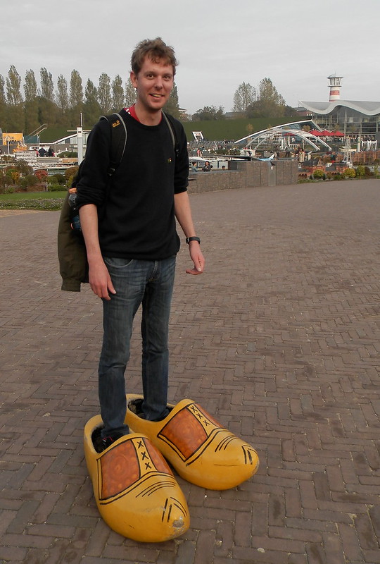
Me in Woodenshoes
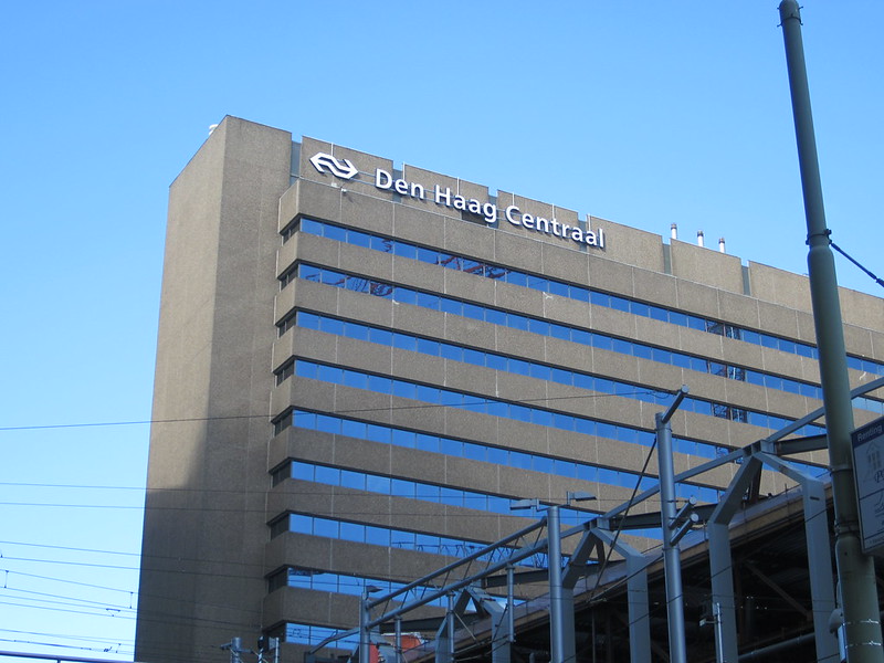
Leiden Centraal
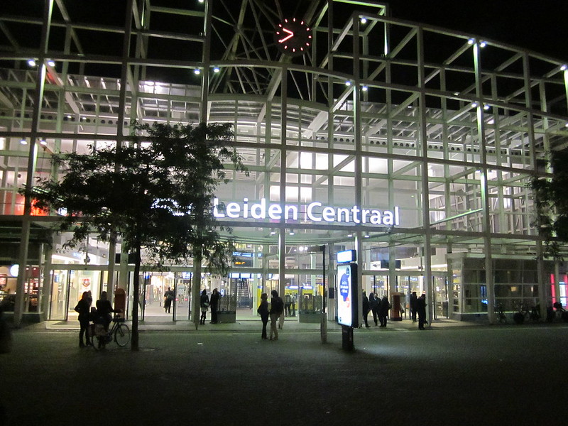
The next Centraal... ;)